
Choosing an electrical connector for demanding operating conditions involves much more than checking dimensions or comparing technical specifications. In aerospace, defense, marine engineering, and other reliability-critical industries, a connector failure can interrupt signal transmission, disrupt power delivery, or affect the performance of an entire system. For this reason, MIL-DTL-38999 Series III connectors are widely used in applications that require dependable electrical connections under challenging conditions.
These connectors are recognized for their rugged construction, compact contact arrangements, and resistance to environmental and mechanical stress. However, not every configuration is suitable for every application. Factors such as operating temperature, electrical load, contact layout, shielding requirements, and installation methods must all be considered before making a selection.
This guide explores the main factors engineers should evaluate when specifying MIL-DTL-38999 Series III connectors and explains how experienced engineering suppliers such as Dconntek can help develop solutions for demanding applications.
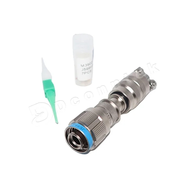
What Makes MIL-DTL-38999 Series III Connectors Suitable for Harsh Environments?
MIL-DTL-38999 Series III connectors are high-performance circular connectors developed for applications where electrical reliability and mechanical durability are essential. Common uses include aircraft avionics, military communication equipment, radar systems, ground vehicles, and industrial control equipment.
One of their distinguishing features is the triple-start threaded coupling mechanism, which enables rapid mating while maintaining a secure connection. Their robust shell construction and shielding design also help protect electrical interfaces against vibration, electromagnetic interference, and other environmental challenges.
Compared with less specialized connector solutions, Series III designs offer a combination of compact packaging, high contact density, and dependable mechanical coupling. These characteristics make them a practical choice for engineers who need reliable connections without excessive installation space.
For additional product details and configuration information, refer to the MIL-DTL-38999 Series III Connector product page.
10 Factors to Evaluate Before Selecting a MIL-DTL-38999 Series III Connector
1. Operating Environment and Protection Requirements
The first step is to identify the conditions the connector will encounter throughout its service life. Connectors installed in aircraft, ships, outdoor equipment, or industrial facilities may be exposed to moisture, dust, corrosive substances, temperature changes, vibration, and mechanical impact.
Before selecting a configuration, consider the following questions:
-
Will the connector operate in areas with high humidity, water exposure, or immersion risks?
-
Could dust, sand, oil, fuel, or other contaminants reach the connection?
-
What temperature range must the connector withstand?
-
Will maintenance require frequent mating and unmating?
Sealing performance depends on the complete connector assembly, not simply the connector family. Shell interfaces, contact seals, rear accessories, cable entries, and installation details can all affect the final level of environmental protection.
Engineers should therefore verify the protection requirements of the assembled interface and confirm that the selected configuration is suitable for the actual operating environment.
2. Electrical Requirements and Signal Transmission
Electrical performance is another essential consideration, particularly in avionics, communication systems, and electronic control equipment. A connector must support the required current and voltage while maintaining reliable signal transmission.
Important parameters include:
-
Contact resistance and its stability during service
-
Rated current and voltage for the selected configuration
-
Signal integrity and potential crosstalk
-
Impedance requirements for high-frequency or high-speed signals
-
Electrical isolation between adjacent circuits
When power and sensitive signals share the same connector, their electrical requirements must be evaluated together. Contact selection, circuit assignment, cable characteristics, and grounding arrangements can all influence performance.
Rather than choosing a connector solely by its total contact count, engineers should check the ratings and limitations of the specific contact arrangement under the intended operating conditions.
3. Contact Layout and Circuit Capacity
MIL-DTL-38999 Series III connectors are available in multiple shell sizes and insert arrangements. Depending on the configuration, they can accommodate different combinations of signal, power, and coaxial contacts.
Selecting the appropriate arrangement requires a clear understanding of the system's wiring requirements and available installation space.
Consider these factors:
-
The total number of circuits required
-
The types and sizes of contacts needed
-
The available space within the enclosure or equipment panel
-
The separation required between power and sensitive signal circuits
-
Potential changes to circuit requirements in future revisions
A connector with insufficient capacity may require additional interfaces, increasing wiring complexity and installation space. Conversely, choosing a configuration that is unnecessarily large can add weight and consume valuable space.
A detailed circuit layout review helps ensure that the connector meets current requirements without introducing avoidable design compromises.
4. Shell Materials and Surface Finishes
The shell material affects connector weight, mechanical strength, and resistance to corrosion. Aluminum alloy is commonly considered where weight reduction is important, while stainless steel may be appropriate for applications requiring particular mechanical or corrosion-resistant properties.
Surface treatment is equally important. Different plating options provide different levels of corrosion protection, conductivity, and shielding performance. Connectors used in marine environments or areas exposed to salt spray may require special attention to material compatibility and surface finish.
When making a selection, engineers should evaluate the complete combination of shell material, plating, environmental exposure, and grounding requirements. The goal is to maintain mechanical integrity and reliable electrical bonding throughout the connector's expected service life.
5. EMI and RFI Protection
Electromagnetic interference (EMI) and radio-frequency interference (RFI) can affect the operation of sensitive electronic equipment. In aerospace and defense systems, where multiple electronic subsystems operate in close proximity, effective shielding is particularly important.
MIL-DTL-38999 Series III connectors use conductive shell designs to support shielding across the connection interface. However, overall shielding effectiveness also depends on the cable assembly and installation method.
Engineers should assess:
-
Electrical continuity between the connector shells
-
The method used to terminate cable braid or foil shielding
-
Grounding and bonding resistance
-
Shielding requirements at the system level
-
Compatibility with applicable EMC test requirements
A connector with suitable shielding characteristics may still perform poorly if the cable termination or grounding path is improperly designed. Reviewing the entire interconnection system helps reduce the risk of interference and signal degradation.
6. Coupling Design and Resistance to Vibration
Mechanical stability is essential in applications exposed to repeated vibration, shock, or movement. The triple-start threaded coupling mechanism used in Series III connectors provides a secure mating interface and allows efficient connection and disconnection.
When evaluating mechanical suitability, consider the expected vibration spectrum, shock loads, mounting arrangement, and maintenance procedures.
The connector must remain securely mated during normal operation while allowing technicians to perform inspections or replacements when necessary. Cable weight, strain relief, and support near the connector should also be considered because excessive mechanical loading can affect long-term reliability.
For mobile equipment and aerospace systems, validating the complete connector and cable assembly under representative mechanical conditions is more useful than evaluating the connector in isolation.
7. Termination Type and Installation Method
The selected termination method influences assembly efficiency, inspection requirements, and field maintenance. Depending on the design, connector interfaces may use crimp contacts, solder contacts, or PCB-related termination arrangements.
Before finalizing the specification, review:
-
Compatibility with the selected wire and cable types
-
Availability of suitable assembly tools
-
Required technician training and assembly procedures
-
Accessibility within the equipment enclosure
-
Inspection, repair, and replacement requirements
Crimp terminations may be suitable for applications requiring repeatable wire-to-contact assembly, provided the specified contacts and tooling are used correctly. Solder and PCB termination methods have their own design and process requirements.
An appropriate termination strategy reduces assembly errors and makes future servicing more manageable. Installation drawings and assembly instructions should be reviewed alongside the connector part number.
8. Custom Configurations and Application Engineering
Standard connector configurations cover many common requirements, but some projects involve unusual wiring layouts, limited installation space, specialized cable assemblies, or combinations of power and signal circuits.
In these situations, application-specific engineering support can help identify a workable configuration before production begins.
Dconntek can be considered as an engineering partner for connector and cable interconnection requirements. Depending on the project, discussions may cover:
-
Alternative contact and insert arrangements
-
Combined power and signal interfaces
-
Connector-to-cable assembly integration
-
Specific sealing and environmental requirements
-
Mechanical compatibility with existing equipment
Customization should be based on clearly defined electrical, mechanical, and environmental requirements. Any proposed modification must also be checked against the applicable specification, qualification status, and project approval process.
Early communication between the equipment designer and connector supplier can help reduce design revisions and avoid compatibility problems during assembly.
9. Qualification Testing and Product Reliability
For mission-critical equipment, a connector's suitability should be supported by relevant technical documentation and test evidence. A general statement of compliance is not always enough to demonstrate that a particular assembly will meet the demands of a specific application.
Depending on the project, verification may include:
-
Temperature cycling and thermal exposure
-
Vibration and mechanical shock testing
-
Salt spray or other corrosion assessments
-
Contact resistance and electrical continuity checks
-
Insulation resistance and dielectric withstand testing
-
Mechanical durability and mating-cycle evaluation
The required tests depend on the applicable specification, product configuration, and end-use environment. Engineers should confirm which tests are covered by existing qualification data and which require additional validation.
Where a project has strict certification or traceability requirements, documentation should be reviewed before the connector is approved for production.
10. Supply Continuity and Product Lifecycle Management
Connector selection should also account for long-term procurement and maintenance. Aerospace, defense, and industrial systems may remain in service for many years, making component availability and configuration control important throughout the product lifecycle.
Before committing to a connector design, consider:
-
The availability of the specified configuration
-
Production lead times and supply continuity
-
Compatibility with existing equipment and replacement parts
-
Traceability and documentation requirements
-
Procedures for managing product changes or obsolescence
Changing a connector after a system has been qualified may require additional testing, documentation, and engineering work. Confirming supply arrangements and maintaining accurate part-number records can help reduce these risks.
Working with a supplier that understands the project's technical requirements and lifecycle expectations can make ongoing procurement and maintenance easier to manage.
Why Engineering Support Matters When Choosing a Connector
Selecting a MIL-DTL-38999 Series III connector is not simply a matter of finding a part number that fits the available space. The connector must work as part of a complete electrical and mechanical system.
Environmental protection, circuit capacity, shielding, cable termination, mounting conditions, and long-term availability all influence the final result. A mismatch in any of these areas can lead to installation difficulties, reduced reliability, or costly design changes.
Engineering-oriented suppliers such as Dconntek can assist customers in reviewing connector requirements, evaluating suitable configurations, and coordinating connector and cable assembly needs. This support is particularly useful when a project involves non-standard wiring, restricted installation space, or demanding operating conditions.
Defining the application requirements early and checking them against the proposed configuration helps engineers make more informed decisions before prototyping and production.
Conclusion
MIL-DTL-38999 Series III connectors are widely used in harsh-environment applications because of their rugged construction, secure coupling design, and ability to accommodate a range of electrical configurations. Nevertheless, selecting the right connector requires a thorough assessment of the conditions in which it will operate.
Engineers should consider environmental sealing, electrical performance, contact arrangement, shell materials, EMI shielding, mechanical loading, termination methods, qualification requirements, and lifecycle support before finalizing a specification.
Combining careful technical evaluation with application-focused engineering support can help reduce integration risks and improve the reliability of the complete interconnection system.
To explore available configurations and product information, visit the MIL-DTL-38999 Series III Connector page.
www.dconntek.com
Dconntek
About Author

You may also like
-
Custom Toroidal Inductors for Specialized Power and Magnetic Applications
-
Custom Walk-In Environmental Test Chamber: Design, Selection, and Application Guide
-
Sapphire Windows for Semiconductor Plasma and Vacuum Equipment: Sourcing the Bare Window Element
-
Engineering-Driven CNC Machining for Automation OEM Projects
-
China High-Precision CNC Fixture Manufacturer: 2026 Overview