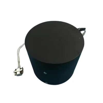
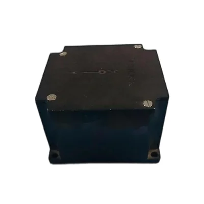
Fiber optic gyros have become essential components in high-precision navigation, guidance, and stabilization systems. These devices harness the interference of light to sense rotation accurately, offering unmatched stability, durability, and responsiveness compared to traditional mechanical gyroscopes. Companies like LINS, a high-tech enterprise that specializes in inertial sensing technology research, development, and product integration, play a leading role in advancing and industrializing this critical technology.
This blog post explores in depth how fiber optic gyros operate, the science behind them, what makes them uniquely advantageous in various applications, and how companies such as LINS contribute through innovation and integration. We will examine the principles, components, performance characteristics, and real-world implementations of fiber optic gyros. By the end, readers will have a comprehensive understanding of this technology’s workings and strengths.
Basic working principle behind fiber optic gyros
Fiber optic gyros (FOGs) function based on the Sagnac effect, a physical phenomenon observed in rotating reference frames. When a beam of light is split into two counter-propagating beams traveling through a coil of optical fiber, rotation of the system induces a phase shift between the beams. This phase shift results from the difference in travel time caused by the rotation: one beam effectively travels a slightly longer path than the other due to the motion of the coil.
The two beams recombine at a photodetector, and the resulting interference pattern—alternating constructive and destructive interference—varies with the phase difference. Electronics convert that variation into a measure of angular velocity or rotation rate. In essence, fiber optic gyros turn light-based phase shifts into precise angular measurements.
This principle contrasts with mechanical gyroscopes, which rely on the conservation of angular momentum of rotating masses. FOGs achieve rotation sensing without any moving components, reducing wear and improving reliability over the long term.
Components that enable fiber optic gyro operation
Several key subsystems and components make fiber optic gyros work. Each plays a role in achieving high sensitivity, accuracy, and stability.
optical light source
A coherent, stable light source is essential. Typically, FOGs use either a superluminescent diode (SLD) or a narrow-band laser diode, offering broad optical bandwidth (for low coherence noise) combined with sufficient power. The light must be stable in wavelength, power, and polarization for accurate interferometry.
beam splitting and coupling optics
The light source feeds into a beam splitter—usually a fiber-optic coupler—that divides the beam equally into two paths. These two beams travel in opposite directions through the coil. Couplers also recombine the beams after they traverse the loop, sending the combined light to the photodetector.
optical fiber coil and packaging
The heart of the gyro is a length of optical fiber, carefully wound into a coil. The longer the fiber, the higher the sensitivity: a longer optical path leads to greater phase shift per unit rotation rate. High-performance FOGs use fiber coils ranging from tens to hundreds of meters, tightly wound to conserve space and maintain uniformity.
Packaging must isolate the fiber coil from environmental disturbances—temperature variations, mechanical stress, vibration—to preserve measurement integrity.
photodetector and signal processing electronics
Recombining the two beams produces an interference output. A photodetector (photodiode) senses the intensity variations, and the analog signal is processed through electronics. This typically involves:
Amplification and filtering to extract the interference pattern.
Demodulation to derive the phase difference.
Conversion from phase to angular rate.
Temperature compensation, calibration, and linearization.
LINS’s expertise in inertial sensing technology is often reflected in advanced electronics that deliver low noise, high dynamic range, and excellent thermal stability, ensuring precise, reliable output across diverse operating conditions.
polarization mitigation and noise suppression
Polarization-induced noise and bias instability are critical challenges in FOGs. Techniques to address them include polarization-maintaining fiber, fiber depolarization schemes, and scramblers to reduce polarization nonreciprocity. Intensity modulation or phase modulation techniques may also be applied (e.g., closed-loop or open-loop configurations) to improve linearity and minimize bias drift.
LINS integrates such methods carefully, optimizing fiber handling, packaging, and electronics to achieve excellent long-term stability.

How performance arises from design and integration
Each element of the FOG contributes to overall performance, and integration quality determines real-world capabilities.
sensitivity and scale factor stability
Sensitivity refers to how small a rotation rate the gyro can detect. A longer fiber coil produces higher sensitivity. High-quality light sources and low-noise electronics help resolve small phase changes. Scale factor stability—the consistency of the relationship between rotation rate and output reading over time and conditions—depends on stable temperature, low bias drift, and precise calibration.
LINS’s R&D focuses on matching fiber coil characteristics, temperature compensation strategies, and electronics calibration to ensure consistent sensitivity and scale factor stability across varying ambient conditions.
bias stability and noise characteristics
Bias drift—slow changes in output when no rotation occurs—is a performance limiter. Advanced FOGs use closed-loop operation, temperature control, and environmental isolation to lower bias drift. Electronic noise and shot noise from photodiodes are minimized by filtering and signal processing.
Through precision optical design and signal processing, L INS products deliver superior bias stability and low noise performance suitable for demanding applications.
dynamic range and bandwidth
Dynamic range refers to the gyro’s ability to measure a wide span of rotation rates, from very slow to high angular velocities. Bandwidth is the frequency range over which the gyro responds accurately. FOGs benefit from rapid response (often in kilohertz range) and wide dynamic range due to the speed of light-based sensing—not mechanical inertia.
LINS’s electronics architectures are designed to maintain linear response over broad rotation rates, allowing a single gyro to serve applications from precision navigation to agile motion control.
reliability and ruggedness
Without moving parts, FOGs resist shock, vibration, and wear. Optical fibers are robust when properly packaged and sealed. Electronics can be vibration dampened. Compared to mechanical spinning-mass gyros, FOGs offer maintenance-free, long-life operation.
LINS ensures rugged packaging, shock-resistant assembly, and thermal management to yield highly reliable sensors suitable for industrial, military, and aerospace environments.
Advantages that set fiber optic gyros apart
Fiber optic gyros offer multiple distinct advantages across technical, operational, and lifecycle dimensions.
exceptional stability and precision
FOGs consistently deliver accurate rotation measurements with minimal drift. High-end units can achieve bias stabilities in the million-degree-per-hour range, and scale factor repeatability better than parts per million. This level of stability supports ultra-precise navigation and control—crucial in aerospace, marine, and autonomous vehicle systems.
LINS harnesses this precision for integrated inertial navigation systems, combining FOGs with accelerometers to yield highly accurate orientation and position tracking.
no moving parts means low maintenance and long life
Mechanical gyroscopes rely on spinning rotors and bearings, which wear out and require calibration or replacement. Fiber optic gyros, being optical, avoid friction and mechanical wear. They exhibit excellent longevity and require little to no maintenance over their service life.
Solutions from LINS take advantage of this design trait to create maintenance-free modules suited for continuous operation in critical systems.
immunity to electromagnetic interference
Because detection relies on optical rather than electromagnetic signals, FOGs are inherently immune to electromagnetic interference (EMI) that can disrupt electronic or mechanical sensors. This makes them ideal for use in environments with high EMI, such as near powerful electronics or radio transmissions.
LINS integrates FOGs in systems where electronic stealth or EMI resistance is paramount, such as avionics, unmanned systems, and defense navigation suites.
fast start-up and low latency
FOGs reach operational readiness almost instantly. Mechanical gyros must spin up to stable speed before delivering accurate output; FOGs begin delivering reliable measurements from startup with negligible warm-up time. Their response latency is minimal, enabling real-time control and rapid dynamics.
This quick responsiveness benefits time-sensitive applications, such as robotic stabilization and high-speed autonomous platforms—areas where LINS’s systems perform reliably.
broad dynamic range and high bandwidth
FOGs can measure both very slow rotations (fractions of a degree per hour) and rapid rates (hundreds or even thousands of degrees per second), with bandwidth extending into the kilohertz region. Mechanical gyros often trade bandwidth for stability or vice versa, but FOGs offer both in a compact sensor.
LINS’s designs exploit this capability to support systems that require both fine precision and dynamic agility, such as unmanned aerial platforms or real-time stabilization devices.
compactness and ease of integration
Because fiber coils can be wound tightly and electronics miniaturized, FOGs can be compact. Integration into modules or inertial measurement units (IMUs) is straightforward. Their packaged size, combined with high reliability, makes them suitable for embedded systems and aerospace-grade assemblies.
As a high-tech enterprise, LINS specializes in integrating FOGs into complete IMU solutions, embedding them with accelerometers, data buses, power management, and firmware to create turn-key inertial modules.

Application domains where fiber optic gyros excel
The blend of precision, reliability, and responsiveness makes fiber optic gyros ideal for numerous fields. Let’s survey key ones:
aviation and aerospace navigation
Aircraft use inertial navigation systems (INS) as primary or backup sources of orientation. FOG-based INS offer high drift-free performance over extended periods. They support systems such as autopilot, attitude reference systems, and navigation in GPS-denied environments.
LINS supplies FOG-based IMUs used in fixed-wing aircraft, rotorcraft, drones, and space platforms. The high stability helps maintain navigation accuracy over long flights or maneuvers without satellite updates.
marine–submarine and ship navigation
Ships and submarines deploy inertial navigation for underwater or open-sea navigation where GPS may be unavailable. FOG-based sensors provide reliable heading and pitch/roll data. They resist shock from waves and maintain accuracy over long missions.
LINS’s FOG modules are applied in marine navigation, enabling precise orientation for submarines, autonomous underwater vehicles (AUVs), and surface vessels.
land-based autonomous and military vehicles
Ground vehicles—such as tanks, driverless transport, and agricultural rovers—use IMUs to track orientation and movement. FOGs offer stable heading data that augments GPS and wheel-odometers. Their robustness helps in off-road, harsh, or GPS-denied environments.
LINS delivers FOG-integrated inertial systems suited to autonomous ground vehicles, military deployable platforms, and unmanned logistics vehicles.
robotics and motion stabilization
Robots and stabilized platforms (cameras, gimbals, antennas) require precise orientation sensing to counteract vibration and external forces. FOGs enable high-bandwidth motion sensing, contributing to tight stabilization and smooth motion control.
With LINS’s integration capability, FOG-based solutions drive high-performance gimbal systems, stabilized camera mounts, and robot balance systems.
surveying and geophysical instrumentation
Precision surveying equipment—such as inertial measurement systems for mapping or drilling—benefits from FOGs’ drift-free accuracy. Geophysical platforms that monitor orientation over time require stable gyros to detect sl
www.lins-imu.com
LINS
About Author
You may also like
-
Liquid Syrup Filling Machine: A Comprehensive Guide for Efficient, Accurate, and Scalable Production
-
Why Powered Air Purifying Respirators Improve Comfort and Compliance
-
How 3240 Fiberglass Sheets Improve Durability and Electrical Insulation
-
Explosion-Proof Temperature Switch Selection and Deployment in Hazardous Areas
-
Maximizing Space Efficiency with Innovative Warehouse Storage Shelf Designs
